Invar Parts for Electron Microscope Stages and Columns
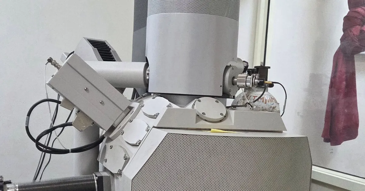
An electron microscope forms an image with a beam a fraction of a nanometer wide, and the picture is only as steady as the structure that holds the sample and the lens. At high magnification, a nanometer is a visible shift, so a frame that grows by a few nanometers per minute as the room warms spoils the image. Low-expansion alloys help, and Invar is one of the candidates. But an electron microscope is a magnetic instrument, and Invar is a magnetic metal. This guide explains where Invar fits and where it must stay away.
Drift, the problem Invar helps with
Every part in the loop between the lens and the sample contributes to thermal drift. The loop is the chain of metal from the pole piece, through the column, the chamber and the stage, to the sample. If its length changes by even a few nanometers during an acquisition, the image blurs or slides.
The size of the effect depends on the length of the loop and its CTE.
| Loop material | CTE (×10⁻⁶ per K) | Change for 100 mm loop at 0.01 K per minute | Change for 100 mm loop per 0.1 K |
|---|---|---|---|
| Aluminum | about 23 | about 23 nm per minute | about 230 nm |
| Stainless steel | about 17 | about 17 nm per minute | about 170 nm |
| Titanium | about 8.6 | about 9 nm per minute | about 86 nm |
| Invar 36 | about 1.3 | about 1.3 nm per minute | about 13 nm |
Typical values for orientation only. The real loop includes several materials and a gradient.
Stage and frame designers use three methods together: a small loop, symmetric structure and low-expansion material in the parts that set the loop length. Invar is useful in the third. The room also matters. A lab held to 0.1 K per hour makes a very different drift than a room that swings by 1 K.
The magnetic problem
An electron beam is steered by magnetic and electric fields. Electromagnetic lenses shape the beam, and any extra magnetic field near the path bends it. Parts in the column, the specimen chamber and the stage are therefore chosen to be non-magnetic or very weakly magnetic, with high-permeability shielding placed on purpose where it is needed.
Invar 36 is ferromagnetic at room temperature. Its Curie point is roughly 230 °C, and below that it carries a magnetic response, which varies with composition and cold work. Placed near the beam, an Invar part can pull the beam off axis, add astigmatism or create a field that moves with the stage. The effect depends on the part’s position and mass and on the instrument’s design, and it can be small or large. Invar magnetic properties and machining covers the behavior in more detail, including how machining and stress change it.
A sensible rule of thumb for electron microscope work:
| Location | Invar suitable? | Typical alternatives |
|---|---|---|
| Inside the column near the beam | Generally no | Non-magnetic stainless, titanium, copper, molybdenum |
| Specimen chamber walls and plates far from the beam | Possible, with magnetic review | Aluminum, non-magnetic stainless |
| Stage base, kinematic frames and metrology loop parts | Often yes, with review | Super Invar, ceramics, titanium |
| External frames, damping platforms and mounts | Yes | Steel, granite, Invar |
| Sample holders for magnetic sample work | Usually no | Titanium, non-magnetic alloys |
Always check the instrument maker’s magnetic limit for each location. Some makers state a maximum field or magnetic moment for stage parts, and a shop can measure its parts against it.
Vacuum cleanliness and baking
Electron microscopes run at high or ultra-high vacuum, and the sample region is kept clean. Parts for the chamber and the stage follow vacuum hardware practice.
- Cleaning. Machining fluids are removed with a validated cleaning process, followed by rinsing, drying and clean bagging. Some users require a vacuum bake before shipment.
- Venting. Blind holes, trapped volumes and screw threads are vented so gas can escape instead of leaking slowly into the chamber. Invar cryogenic and vacuum applications lists the usual details.
- Material choices. Zinc, cadmium and other high-vapor-pressure platings are excluded. If a coating is used, nickel is the common choice and must be clean and well bonded.
- Burrs and particles. Loose particles on a stage contaminate the sample and the beam. Deburring Invar without residual stress describes clean ways to finish edges.
Bakeout, a heating cycle at 100 to 200 °C to drive off water and gas, is used for ultra-high vacuum systems. A bake in this range is below Invar’s knee and does not harm the alloy, but it can change a part that was stabilized by a hold at 95 °C if the bake runs longer or hotter. The shop should know the bake plan before choosing the stabilization cycle, and the final inspection should follow the last bake, as Invar stress relief in machining and the stabilization notes advise.
Typical Invar parts in microscope hardware
Where Invar is accepted, it appears in parts that set position or support a structure.
- Stage base plates and metrology frames that carry the interferometer or encoder mounts
- Kinematic mounts and flexure blocks between the chamber and the stage
- Reference blocks and targets for alignment and calibration
- Mounting frames for detectors and cameras that sit outside the beam path
- Support structures for cryogenic sample stages, where thermal contraction matters and magnetic limits are relaxed
Each of these follows the standard sequence of rough, stress relieve, finish, stabilize and inspect at 20 °C. Because the instrument is a research tool, the quantity is often one to a handful, which suits the approach in Invar research lab custom instrument machining.
Hypothetical worked example
A research group is building a custom sample stage for a scanning electron microscope. The stage metrology frame is a 120 mm span between two kinematic seats. The room is controlled to 0.1 K per hour. Numbers are hypothetical.
- With an aluminum frame, a 0.1 K per hour drift gives about 0.28 µm per hour, or about 4.6 nm per minute, over 120 mm.
- With an Invar frame, the same drift gives about 0.016 µm per hour, or about 0.26 nm per minute.
- The group measures the magnetic response of a test piece of the same Invar with a gaussmeter at the planned position and finds it within the maker’s limit. They place the frame 80 mm from the beam axis.
- The frame is machined, stress relieved, stabilized and baked at 150 °C, then final inspected.
- The first scan after installation shows drift under 1 nm per minute, which meets the acquisition requirement.
If the magnetic reading had been high, the group would have moved the Invar part farther from the beam or changed the frame to a non-magnetic low-expansion material such as a ceramic.
Low-expansion options when magnetism is a problem
Because Invar and its relatives, including Super Invar and Kovar, are all ferromagnetic at room temperature, a design that cannot accept any magnetic response needs another route. The usual choices are:
| Option | Strength | Limit |
|---|---|---|
| Glass-ceramic (Zerodur, ULE) | Near zero CTE, non-magnetic | Brittle, cannot be machined like metal, costly |
| Silicon carbide and other technical ceramics | Stiff, stable, non-magnetic | Brittle, long lead time, see Invar vs silicon carbide |
| Titanium | Non-magnetic, light, available | CTE of about 8.6, moves more |
| Non-magnetic stainless | Common, easy to source | CTE of about 16 to 17, moves most |
| Carbon fibre composite | Light, near-zero CTE possible | Moisture and vacuum effects, see Invar vs carbon fibre |
| Invar placed far from the beam | Keeps the low CTE | Needs a magnetic review and distance |
Many designs combine them: a ceramic or titanium core near the beam and an Invar frame in the outer loop. The combined drift is then set by the part of the loop with the largest CTE, so the designer asks where in the loop the length is concentrated and puts the stable material there.
Cryogenic and variable-temperature stages
Some microscope stages cool the sample to low temperature or heat it. A cryogenic holder pulls heat out of a small region, and the surrounding structure sees a gradient. Differences in contraction between the cold holder and the warm frame cause drift and stress. Invar contracts little on cooling, which makes it useful for parts that tie a cold element to a warm frame, as long as the magnetic limit is met. Above and below room temperature the CTE of Invar changes, with a minimum near room temperature and a rise as the alloy warms toward its knee, so designers check the mean CTE over the actual range rather than relying on the room temperature value. Invar 36 CTE versus temperature shows the curve.
Demagnetizing and measuring
A part with a magnetic response near the limit can sometimes be improved. A demagnetizing cycle after machining reduces the remanent field. A magnetic measurement with a gaussmeter or magnetometer on the finished part confirms the result. Typical practice:
- Keep steel tools and magnetic chucks away from the finished part, or demagnetize afterward
- Measure remanence at a stated distance with a calibrated gaussmeter
- Record the value in the inspection report and ship with a clear label
Invar machined on a magnetic chuck can pick up a field that persists until demagnetization. A drawing for a magnetically sensitive part should say that, and name the limit.
Planning the order of operations
A part for a microscope stage has more constraints than most, and the order of operations matters. Rough machining and the first stress relief come first. Finish machining follows, with the magnetic limit in mind: avoid magnetic chucks for the last cuts, or demagnetize after them. The stabilization hold comes next, then final lapping or grinding of the interface faces. Cleaning and the bake come last, followed by inspection at 20 °C and magnetic measurement. If the bake can shift dimensions by a micrometer, the final inspection must follow it, which means the shop needs access to the bake oven or a partner who runs it. Settling this at the quote stage avoids a part that passes inspection and then changes in the customer’s chamber.
What to put in the RFQ
- The location of the part relative to the beam and the maker’s magnetic limit
- Drift budget and loop length
- Cleaning, venting and packing requirements
- Bake temperature and time, and the stabilization plan
- Demagnetization and magnetic measurement requirements
- Flatness, position and surface requirements on the interfaces
Send the drawing through the RFQ form with the magnetic limit and the bake plan stated, and we match you with shops that machine vacuum-clean Invar parts for instruments. For handbook values see the Invar reference data, the Invar 36 machining page and Invar beamline vacuum chamber machining for related vacuum work.
Frequently asked questions
Can Invar be used inside an electron microscope column?
Only with care. Invar 36 is ferromagnetic at room temperature, and magnetic material near the electron beam distorts the lens fields and the image. Parts in or close to the beam path are usually non-magnetic. Invar is better suited to stage frames, base plates, metrology frames and mounts that sit well away from the optics, or where the magnetic effect has been measured and accepted.
Why does thermal drift matter so much in an electron microscope?
At high magnification, one nanometer of sample movement is visible in the image. A stage or frame that grows by a few nanometers per minute as the room warms makes the image slide. Low-expansion frames and a stable room reduce the drift, and they reduce the time the operator must wait for the system to settle before an acquisition.
Can Invar parts be baked for ultra-high vacuum?
Yes, within limits. Typical bake temperatures of 100 to 200 °C stay below the stabilization and Curie regions that matter, but a long hot bake can change the stabilization state of a part that was stabilized at lower temperature. The drawing should state the bake temperature and time, and the final inspection should follow the last bake.
Reviewed against
Values in this guide are typical handbook figures for planning. The mill certificate for your heat lot and the shop's quote for your geometry govern.
Need a quote for this part?
Send the drawing. We match you with up to 3 shops that machine Invar and reply within 24 business hours.
Get matched with an Invar shop